Understanding why cell format, energy density, and pressure relief design are the most critical factors in lithium battery safety April 2026 At Deep Cycle Systems, safety is not a feature — it is the foundation of every engineering decision we make. Since our founding, DCS has exclusively used cylindrical lithium iron phosphate (LFP) cells across almost our entire 12V and 24V battery range. This is a deliberate choice rooted in physics, not marketing. This document explains the technical reasons why DCS limits its 12V and 24V battery capacities to a maximum of 200Ah, and why we will never exceed this threshold. The answer lies in three interconnected engineering principles: DCS Position Statement: We will never manufacture a 12V or 24V battery larger than 200Ah. To do so with cylindrical cells would require compromises in pack geometry and thermal management that conflict with our safety-first engineering philosophy. Manufacturers offering 300Ah, 400Ah, or larger 12V batteries are using large-format prismatic cells — a fundamentally different and higher-risk architecture. There are two primary cell formats used in lithium battery manufacturing: cylindrical and prismatic. While prismatic cells offer higher volumetric energy density (more Ah per litre), cylindrical cells offer critical safety advantages that DCS considers non-negotiable for mobile and off-grid applications. In vehicles, boats, caravans, and off-grid setups, batteries are subjected to continuous vibration, mechanical shock, temperature cycling, and the real-world risk of improper installation or charging. Cylindrical cells are inherently more tolerant of these conditions due to their curved geometry, which distributes mechanical stress evenly around the cell wall rather than concentrating it on flat surfaces. Every lithium cell contains a pressure relief valve (PRV) — also called a safety vent or CID (Current Interrupt Device). When internal pressure rises due to overcharge, short circuit, or thermal abuse, the PRV is designed to open and safely vent gases before pressure reaches catastrophic levels. The effectiveness of a PRV depends on a critical relationship: the ratio of the vent area to the internal volume of the cell. Cylindrical vs Prismatic cell PRV effectiveness. The cylindrical cell’s smaller volume and higher PRV-tovolume ratio ensures reliable pressure relief every time In a cylindrical 20Ah cell, the internal volume is approximately 70 cm³. The PRV occupies a significant proportion of the cell’s end cap, giving it an excellent vent area-to-volume ratio. When internal pressure rises, gas generation is relatively slow (due to the small amount of active material), and the PRV has ample time to open and vent safely. In a prismatic 280Ah cell, the internal volume is approximately 1,800 cm³ — roughly 25 times larger. Yet the PRV is only marginally larger. The result: DCS Engineering Principle: By using 20Ah cylindrical cells, the PRV has a perfect chance to open in time, every time. The physics of small-volume gas generation combined with an appropriately-sized vent makes reliable pressure relief a near-certainty — not a probability. Thermal runaway occurs when the energy released by an exothermic reaction within a cell exceeds the cell’s ability to dissipate heat. The total energy available to drive this reaction is directly proportional to the energy density of the cell. DCS cylindrical LFP cells operate at approximately 160–180 Wh/L — roughly half the energy density of typical prismatic LFP cells (280–350 Wh/L). This is not a limitation; it is a deliberate safety margin. Consider what happens during a worst-case internal short circuit: Key Insight: At approximately half the energy density of prismatic cells, DCS cylindrical cells are physically unable to generate sufficient heat to sustain thermal runaway. The energy simply is not there. This is not a theoretical advantage — it is a thermodynamic certainty. DCS battery packs use a proprietary cell interface resin stabiliser that fills the interstitial spaces between cylindrical cells within the pack. This resin serves three critical functions: A DCS 200Ah battery pack at 12.8V contains 40 individual 20Ah cylindrical cells arranged in a 4S10P configuration (4 in series × 10 in parallel). This represents the practical maximum for a pack that maintains: Exceeding 200Ah would require either: DCS refuses to accept either compromise. Industry Warning: Manufacturers offering 12V batteries rated at 300Ah, 400Ah, or higher are using large-format prismatic cells. These cells contain 5–16 times more energy per cell than DCS cylindrical cells, have less effective pressure relief characteristics, and rely on pack-level safety systems to compensate for cell-level risks. DCS believes safety must begin at the cell level. Every lithium cell ages. Over time, internal resistance rises, capacity fades, and the cell’s ability to deliver current diminishes. This is unavoidable chemistry. However, the consequences of cell ageing are dramatically different depending on pack architecture — and this is where large single-battery packs face their most serious long-term vulnerability. In any battery pack, the weakest cell dictates the performance of the entire pack. As cells age, they do not age uniformly — some cells degrade faster than others due to minor manufacturing variations, uneven thermal exposure within the pack, and micro-differences in internal chemistry. Over hundreds of charge cycles, these small differences compound. In a large-format prismatic pack (e.g., a single 400Ah battery using four 100Ah prismatic cells in series), the consequences are severe: In a DCS 200Ah battery with 40 individual cylindrical cells in a 4S10P configuration, cell ageing has a fundamentally different — and far less damaging — impact: The Hidden Cost: A single 400Ah prismatic battery may appear cheaper upfront than two DCS 200Ah batteries. But when cell ageing causes premature capacity loss — often well before the expected service life — the customer must replace the entire unit. With a DCS parallel system, the modular architecture means longer effective service life, more predictable degradation, and lower total cost of ownership. When customers require more than 200Ah of capacity, the instinct may be to look for a single larger battery. However, running two DCS 200Ah batteries in parallel to create a 400Ah bank is not just the safer option — it is the technically superior option in every measurable way. When two batteries are connected in parallel, the load current is split equally between them. This has a profound effect on internal heat generation. Heat generated inside a battery is governed by I²R losses (Joule heating) — the power dissipated as heat across the internal copper busbar network, cell connections, and BMS MOSFETs is proportional to the square of the current flowing through them. Halving the current through each battery reduces heat generation to just one quarter of what a single battery would experience at full load. The Physics: Because heat scales with the square of current (I²R), splitting the load across two batteries doesn’t just halve the heat — it quarters it in each battery. The copper busbar network, laser-welded cell connections, and BMS MOSFETs all run significantly cooler. Cooler operation means longer component life, more consistent cell performance, and a wider safety margin under sustained high-current loads such as inverters, winches, and trolling motors. Crucially, this reduced thermal stress also slows the rate of cell ageing — compounding the longevity advantages described in Section 6. DCS batteries achieve their industry-leading safety profile through three reinforcing layers of protection: The DCS Promise: Every DCS battery is built from cells that are individually incapable of catastrophic failure. When you choose DCS, you’re not relying on software, sensors, or BMS systems to keep you safe — you’re relying on physics. Our BMS provides monitoring, balancing, and protection as additional layers, but the fundamental safety of a DCS battery begins at the cell level. DCS supports parallel connection of up to 10 batteries, enabling systems up to 2,000Ah while maintaining full safety compliance. Each battery in a parallel array operates independently with its own BMS, cell management system, and protection circuits. A failure in one battery cannot propagate to another. As demonstrated in Sections 6 and 7, parallel operation is not a compromise — it is the thermally superior architecture that also ages more gracefully. Two 200Ah batteries in parallel will always outperform a single 400Ah battery in heat management, longevity, and safety. The more batteries in your parallel bank, the cooler each one runs — and the slower each one ages. This modular approach provides:Why DCS Will Never Manufacture Batteries Larger Than 200Ah
A Technical Safety White Paper on Cylindrical Cell Architecture
Executive Summary
1. Why Cylindrical Cells: The Physics of Safety
1.1 Cell Format Comparison
Parameter
DCS Cylindrical (LFP)
Typical Prismatic (LFP)
Individual cell capacity
3.2V × 20Ah = 64Wh
Energy density
~160–180 Wh/L
Energy per cell failure event
64 Wh (safe, manageable)
PRV effectiveness
Thermal runaway propagation risk
Extremely low
Moderate to high depending on pack design
Mechanical robustness
Lower — flat walls susceptible to deformation
1.2 The Cylindrical Advantage in Mobile Applications
2. Pressure Relief Valve (PRV) Design: Why Size Matters
2.1 How PRVs Prevent Thermal Runaway

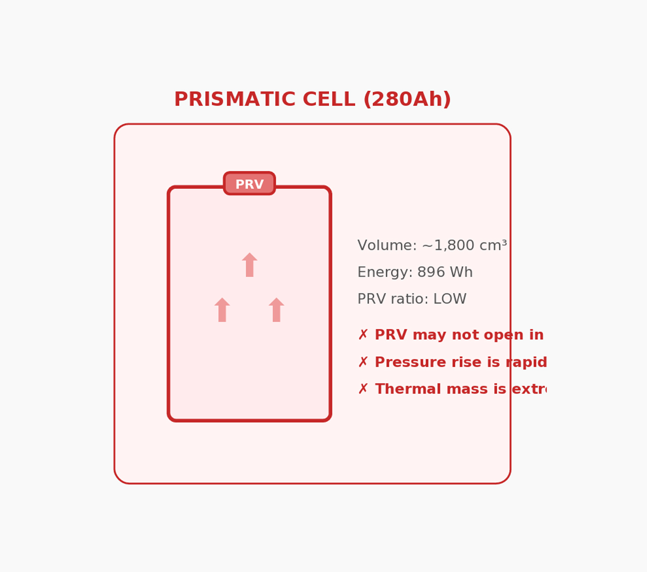
2.2 The PRV-to-Volume Ratio
3. Energy Density: Why Lower Is Safer
3.1 The Thermal Runaway Equation

3.2 What This Means in Practice
Scenario
DCS Cylindrical 20Ah Cell
Prismatic 280Ah Cell
Total energy in failing cell
64 Wh
896 Wh
Energy density
~170 Wh/L
~320 Wh/L
Gas generation rate
Slow, controlled venting via PRV
Rapid, potentially exceeding PRV capacity
Propagation risk to adjacent cells
Significant — direct face-to-face contact transfers heat
Outcome
Potential cascading failure across the pack
4. Cell Interface Resin Stabiliser: Isolation by Design

5. Why 200Ah Is the Engineering Limit
6. The Cell Ageing Problem: Why Large Single Packs Decline Rapidly
6.1 The Weakest Cell Problem
6.2 Why Smaller Cells Age More Gracefully
6.3 The Ageing Cascade in Large Prismatic Packs
Ageing Stage
Large Prismatic Pack (4 × 100Ah)
Early life (0–500 cycles
All cells perform well; minor differences not yet apparent
All cells perform well; active balancing keeps strings matched
Mid life (500–1500 cycles)
Centre cells running hotter begin degrading faster; capacity spread between cells widens; BMS starts limiting performance to protect weakest cell
Minor capacity spread across 40 cells; active cell management compensates; pack performance remains near-original
Late life (1500+ cycles)
Weakest cell becomes severe bottleneck; pack capacity drops rapidly; charge acceptance declines sharply; entire pack may need replacement despite 3 healthy cells
Gradual, even decline across 40 cells;pack still delivers strong performance; individual cells can be serviced if needed in DCS aluminium cases
7. The Parallel Advantage: Why 2 × 200Ah Beats 1 × 400AH
7.1 Current Sharing and Heat Reduction
Figure 4: Heat Generation — Single 400Ah vs 2 × 200Ah Paralle
Single 400Ah Prismatic
Configuration
One battery, full load
Two batteries, load split evenly
Current per battery
200A through one pack
100A per pack
Heat formula
I²R = 200² × R = 40,000R
I²R = 100² × R = 10,000R each
Heat per battery
40,000R watts
10,000R watts ✓
Heat reduction
—
75% less heat per battery
Total system heat
40,000R
Copper busbar temp
High — concentrated current
BMS MOSFET stress
High — single BMS, full load
Low — each BMS at half load
Lifespan impact
Accelerated degradation from heat
Extended life — cooler operation
Redundancy
None — total loss on failure
Serviceability
Entire bank replaced
Individual battery can be swapped
8. Summary: Three Layers of Safety
Safety Layer
DCS Approach
1. Cell Format
3.2V 20Ah cylindrical LFP cells
2. Pressure Relief
High PRV-to-volume ratio with proven cylindrical vent design
3. Energy Density
Lower energy density means the cell physically cannot store enough energy to sustain thermal runaway. This is a thermodynamic limit, not a design feature that can fail
9. For Customers Who Need More Than 200Ah
The DCS Safety Commitment
3.2V × 100–320Ah = 320–1,024Wh
~280–350 Wh/L
320–1,024 Wh (significant thermal mass)
Excellent — geometry ensures rapid, reliable venting
Variable — large flat surfaces resist deformation
High — curved walls resist crush and impact
Peak temperature potential
Low — insufficient energy to sustain runaway
High — sufficient energy to propagate to adjacent cells
Negligible — cell interface resin absorbs and isolates heat
Single cell vents safely; pack continues operating
DCS Cylindrical Pack (40 × 20Ah)
2 × 200Ah DCS Parallel
20,000R (50% less)
Low — distributed current
50% capacity retained if one offline
Why It Matters
Small individual cells (64 Wh each) ensure any failure event is inherently limited in energy. The curved cell wall resists mechanical deformation from vibration and impact.
The small internal volume of each cell ensures the PRV can vent gases faster than pressure builds — guaranteeing reliable operation every time.
~170 Wh/L — approximately half of prismatic equivalents

Related Blogs